Machine operation and automation
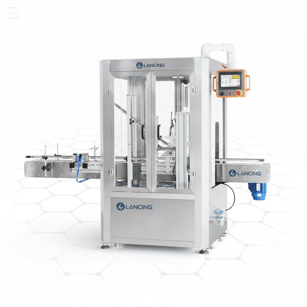
How does a jar capping machine work?

Find direct, practical answers about jar capping machines, screw and twist-off closures, vacuum processes, lid feeding, container handling, line integration, trials and project acceptance.
Use representative evidence. Machine suitability still depends on the actual jar, lid, product, process and acceptance method.
The resource layer links concise answers to the deeper machine, process and acceptance guidance already available on this website.
How does a jar capping machine work?
Twist-off or continuous-thread screw lid?
Dry vacuum or steam-flow capping?
How are jars stabilised during capping?
How should a food jar capper be cleaned?
What belongs in a procurement specification?
Send representative jars and lids with the product and process description, target accepted output, line layout and the checks used to release a finished pack. This gives the technical review a defined starting point.
Send your project detailsNo. A cap-presence sensor can confirm that an object matching the detection method is in the expected position, but it does not prove torque, lug engagement, vacuum, leakage or product-specific seal integrity.
Use presence or height as one control within a defined inspection plan and retain the approved offline or process-dependent checks needed for the closure.
The line should track the failed jar from the inspection point to the reject station and obtain a separate confirmation that the intended jar entered the reject path.
The specification should also cover a full reject bin, failed confirmation, manual sample removal, sensor bypass and reconciliation of entered, accepted and rejected counts.
The most useful figure is accepted good jars over an agreed elapsed production period, with normal refill, inspection, short stops, operator tasks and reject categories included.
A brief peak speed can support mechanical setup but cannot by itself predict shift capacity or identify the real line constraint.
Cap-feeder stops should remain visible in the complete capping-cell result, while also being coded separately from capping-head, jar-supply and downstream losses.
This shows whether the requested automation includes a stable lid supply and prevents a fast tightening head from masking poor closure presentation.
Choose around cap placement, jar movement, closure contact, changeover and the quality checks used to accept a pack. A chuck normally applies a matched tool from above; spindle wheels normally tighten continuously while the jar moves inline. Compare both routes.
No. A compatible foil-lined screw cap is normally placed and tightened first so the liner contacts the finish. The capped jar then passes through the induction process. Review the complete sequence.
The best route depends on whether the closure can be oriented reliably, transported without marking and handed to the jar under control across refill and speed variation. Compare manual placement, bowls, elevators, rotary orientation and assisted tracks using production closures.
No. Induction energy does not correct poor thread engagement, uneven liner contact or product on the finish. The capper and sealing stage should be validated together.
Use every production cap, record fill level and refill, challenge wrong orientation, follow the cap through track and handover, and count damaged, missed and incorrectly placed closures. The trial should continue through the capper.
Accepted output includes the effects of feeder refills, stops, restarts, changeovers and rejected packs. It therefore describes the production result more usefully than a theoretical cycle rate measured without normal losses.
Send your jar, lid, product and target output. Lancing will help you identify a practical machine route and the samples needed for confirmation.