Semi-Automatic Screw Jar Capper
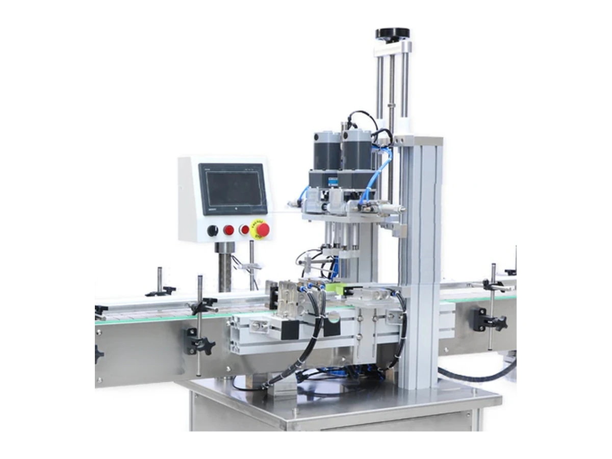
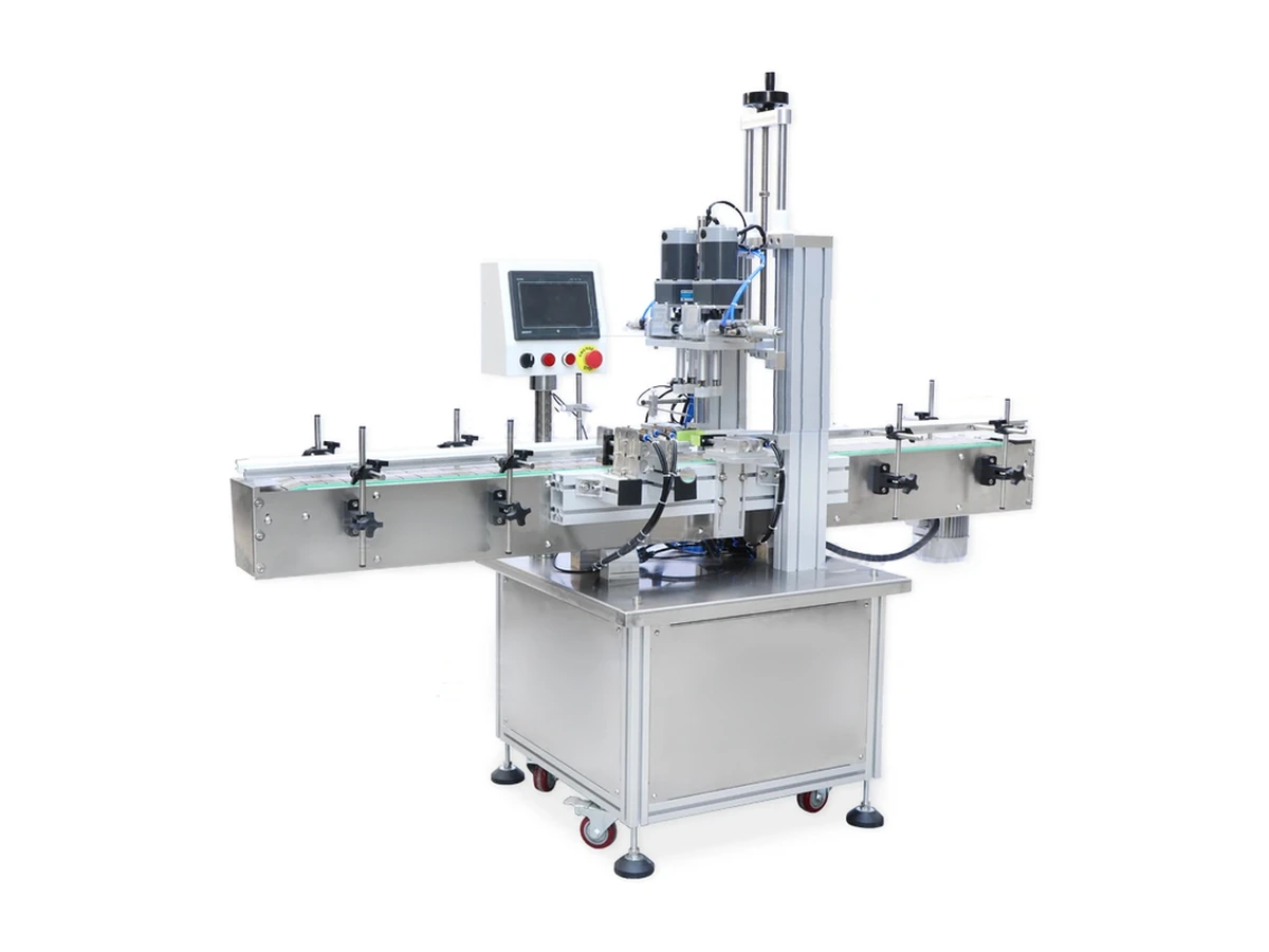
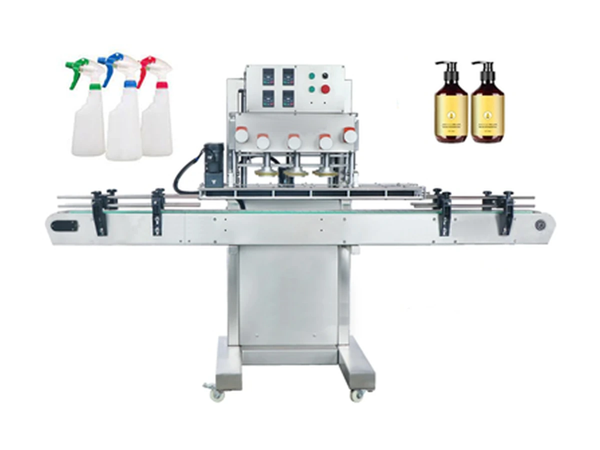
A compact screw-capping route for smaller batches where an operator places the lid and the machine provides controlled bottle support and repeatable tightening.
Compare operator-assisted, compact automatic, inline screw, spindle, twist-off and bowl-fed routes, then narrow the choice using your production jars, lids and target output.
Start with real samples. Your jar, lid and target output provide a more reliable recommendation than choosing by model number alone.

Published ranges help narrow the options, but cap geometry and seal behaviour can rule a machine in or out even when the nominal diameters appear to fit.

A compact screw-capping route for smaller batches where an operator places the lid and the machine provides controlled bottle support and repeatable tightening.

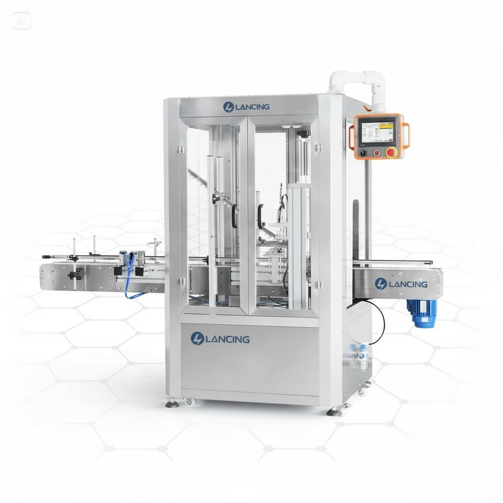
A compact inline screw capper for jar projects that need conveyorised handling and repeatable tightening without the footprint of a larger high-speed spindle system.

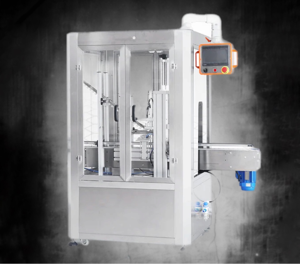
An inline screw-capping platform for jars and containers using threaded closures, with adjustable bottle handling and controlled cap tightening for repeatable production.

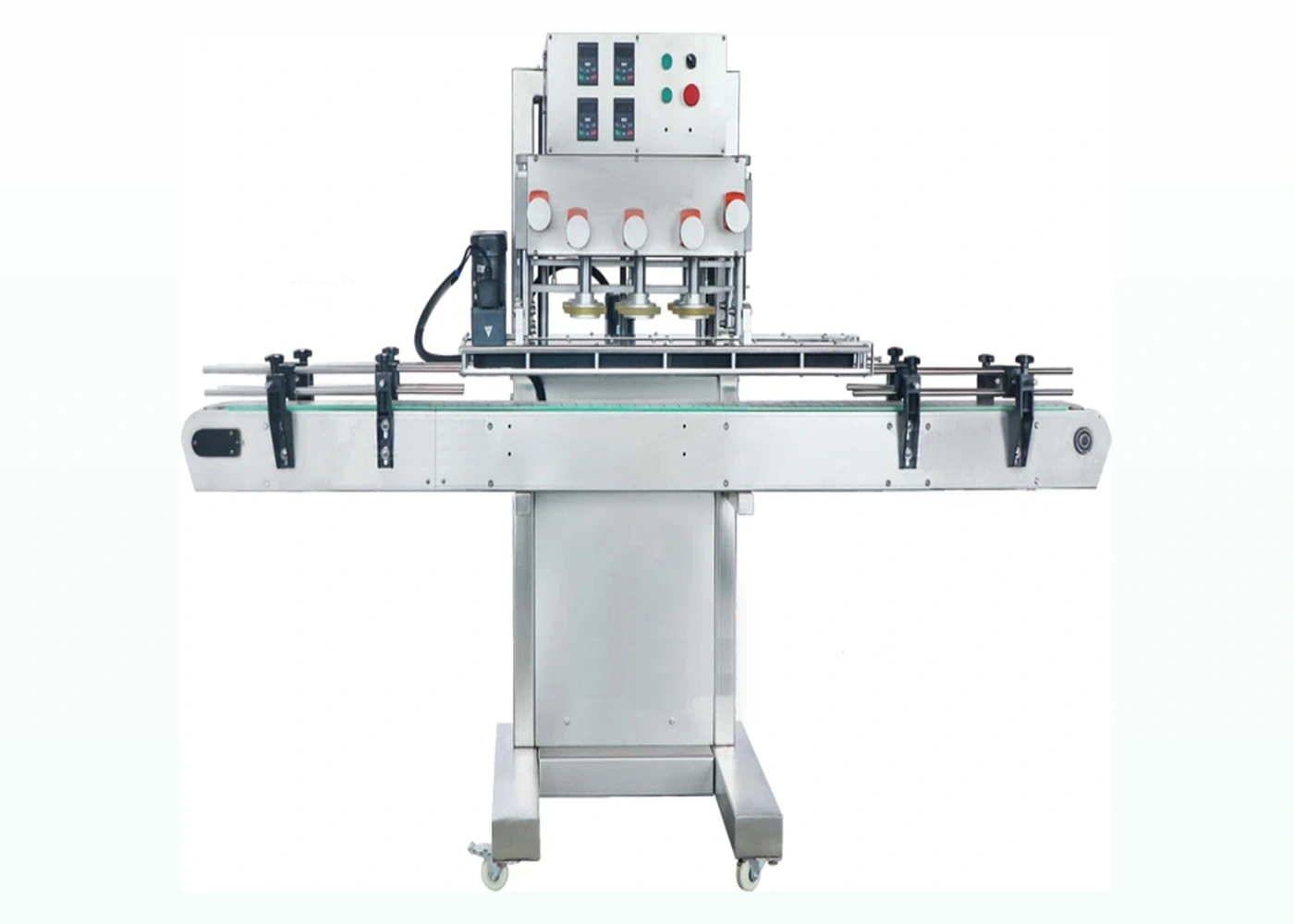
A continuous belt-and-spindle capping route for threaded jar lids where side-belt control, multiple tightening stages and higher line output are priorities.

An automatic feeding and capping route for metal twist-off closures commonly used on glass jars, specified around lid presentation, downward force, closure engagement and finished seal requirements.

A screw-capping system with a vibratory bowl feeder for projects where loose lids can be sorted, oriented, delivered and applied automatically before tightening.
| Closure / requirement | Likely machine route | Critical checks |
|---|---|---|
| Continuous threaded lid | Chuck, compact inline or spindle screw capper | Thread start, cap grip, torque, jar squeeze and side support |
| Metal lug / twist-off lid | Dedicated twist-off application and sealing route | Lug engagement, liner compression, fill temperature, vacuum and cap height |
| Wide decorative screw lid | Application-specific chuck or controlled inline capper | Marking, skirt distortion, low torque, cap diameter and jar stability |
| Bulk loose lids at higher speed | Bowl, elevator or other closure feed before the capper | Orientation, nesting, finish damage, buffer capacity and changeover |
| Short batches and many SKUs | Semi-automatic capper with manual lid placement | Operator cycle, tool change, batch records and repeatable settings |
The machine supports the jar and applies a controlled capping cycle. This route prioritises flexibility and lower capital cost.
Compare semi-auto machinesJars travel by conveyor through a capping station. Lid placement may still be manual or handled by an upstream device.
Compare automatic cappersA dedicated feeder, chute and placement system supply closures to the capper for repeat automated production.
Review cap feeding
Compare closure type, jar dimensions, output, cap presentation, torque or vacuum requirement, changeover frequency and integration needs.
Send jars, lids, fill conditions, target speed, accepted seal checks, utilities, floor space and details of any existing filler or conveyor.
No. Indicative outputs are indicative. Actual capability is confirmed after testing the production jar, lid, cap feed and line spacing.
The figures below are consolidated from the individual machine pages in this website. They are shortlist data, not a substitute for a sample trial and signed project specification.
| Machine route | Published jar or lid range | Indicative output | Closure feeding | Torque or vacuum basis | Changeover focus |
|---|---|---|---|---|---|
| Semi-automatic screw jar capper | Cap Ø20–60 mm; jar height 100–300 mm | 20–60 containers/min, format and operator dependent | Manual lid placement | Target and verification method confirmed against the approved pack | Chuck/tooling, height, clamp position and recorded settings |
| Compact automatic jar capper | Cap Ø18–70 mm; jar height 60–270 mm | Approximately 20–40 containers/min, format dependent | Application-specific placement or feeder interface | Project-specific torque window; no universal published value | Guides, head/tooling, conveyor and stored setup record |
| Automatic jar screw capper | Cap Ø18–70 mm; jar Ø20–160 mm; height 30–300 mm | 20–60 containers/min, product and format dependent | Project-specific cap presentation | Measured closure result confirmed by sample trial | Jar guides, cap handling, height, head and line controls |
| Automatic spindle jar capper | Jar approximately Ø35–120 mm; height approximately 60–200 mm | 3,000–5,000 containers/hour, format dependent | Pre-placed threaded lids | Progressive tightening settings verified by removal-torque testing | Side belts, spindle wheels, guides, height and cap presentation |
| Automatic twist-off jar capper | Published lid outside diameter Ø30–80 mm | 30–40 jars/min, format dependent | Automatic lid feeding and presentation | Vacuum and seal limits belong to the validated jar, lid and product process | Lid feed tooling, jar guides, capping settings and process conditions |
| Automatic jar capper with vibratory bowl | Cap Ø18–70 mm; container Ø20–160 mm | 20–60 containers/min, format dependent | Vibratory bowl sorting, orientation and delivery | Project-specific torque or seating requirement confirmed by trial | Bowl tooling, track, chute, guides, head and sensors |
Published ranges overlap, but that does not prove that every jar-and-lid combination inside a range will feed, grip or seal correctly. Production samples and an agreed acceptance method remain essential.
This website owns jar-specific selection. For broader bottle screw-capping machinery, pumps and other threaded bottle closures, use the dedicated screw-capper resource.
Visit Screw Cappers UKJar pages cover the feeder-to-capper interface. For bowl feeders, elevators, sorters and specialist closure orientation across wider capping applications, use the cap-feeder resource.
Visit Cap Feeders UKThis site covers the jar-capping stage and its immediate interfaces. For full filling, labelling, conveying and end-of-line coordination, use the packaging-line resource.
Visit Packaging Lines UKPublished size and output ranges help remove clearly unsuitable options, but the operating model usually determines whether a machine will fit the production process. The same closure may be compatible with more than one route while requiring very different labour, floor space, changeover and control arrangements.
| Machine route | Operator and lid presentation | Best evidence of fit | Limitation to confirm |
|---|---|---|---|
| Semi-automatic chuck capper | The operator presents the jar and normally places the lid before a controlled tightening cycle. | Timed runs with normal operators, representative packs and recorded removal-torque results. | Ergonomics, hand placement consistency and achievable sustained rate across the working period. |
| Compact inline capper | Jars travel on a conveyor; lid placement can remain manual or use an application-specific feed interface. | Stable transfer, repeatable seating and a line-rate test including normal stops. | Available conveyor length, jar pitch, lid placement and access for adjustment. |
| Spindle capper | Threaded lids normally enter pre-placed and are tightened progressively while side belts control the container. | Filled-jar stability, progressive tightening and torque distribution during a sustained run. | Suitable side-wall contact, lid grip profile and reliable pre-placement. |
| Automatic twist-off capper | Compatible metal lug lids are fed and applied as part of a defined sealing process. | Feed reliability, lug engagement and finished vacuum or integrity checks at the agreed time. | Jar/lid/process compatibility; a nominal lid diameter alone does not prove a valid seal. |
| Bowl-fed automatic capper | Loose closures are sorted, oriented, buffered, placed and tightened with minimal routine hand placement. | Bulk-lid trials covering refill, low-level, stop/restart and changeover conditions. | Closure nesting, marking, orientation features, bowl tooling and jam-recovery access. |
Ask each proposed route to demonstrate the same pack conditions, acceptance method and sustained production duty. This prevents a fast empty-jar demonstration from being compared with a filled-jar run that includes cap replenishment, minor stops and quality sampling.
Plan sustained output · Use the closure-led selection guide · Arrange a sample review
Screw, twist-off and vacuum routes describe the closing technology, but the final configuration also depends on who places the lid, whether closures are supplied from bulk, how the jar is stabilised and which finished-pack check releases production. A machine comparison is incomplete until those boundaries are explicit.
Use the jar and lid compatibility guide to confirm the pack, then compare manual, semi-automatic and automatic operation. Procurement teams can use the quotation cost-factor guide to keep unlike scopes from appearing directly comparable.
Machine labels can overlap. A sound comparison starts with the closure and finished-pack requirement, then defines how jars and lids will be presented and checked.
Diameter confirms only part of the physical envelope; it does not confirm thread form, lug geometry, skirt depth, liner, grip surface, jar stability or required closing process.
Two closures with a similar outside diameter can need different tooling, feeding and acceptance methods. Production samples reveal friction, finish variation, nesting, marking risk and how the jar behaves under load, which a diameter value cannot show.
The automation boundary should be set where it removes a proven production constraint without adding unjustified feeding, handling or changeover complexity.
Define who loads jars, who presents lids, whether the capper spaces containers, how rejected packs leave the line and which machine controls start, stop and fault conditions. A compact automatic capper with manual lid placement can be the right boundary for one process, while another needs bulk feeding and full line handshakes.
Overlapping published ranges mean the machines may physically accept similar diameters, not that they will perform the same closing task.
Compare the closure family, gripping method, torque or vacuum principle, jar support, cap presentation, change parts and the evidence required at acceptance. The actual jar-and-lid combination remains the deciding test.
Buyers should compare the complete capping cell whenever feeding, stabilisation, controls or inspection are necessary to achieve accepted output.
A low-cost head may not include the conveyor, guides, side belts, cap placement, sensors, guarding, rejects, line signals or format parts needed in production. Ask each supplier to state the complete supply boundary, exclusions and acceptance method.
Provide a format matrix showing every jar, every lid, the required process, target sustained output, change frequency and whether lids arrive loose, nested, pre-placed or already oriented.
Send your jar and lid detailsMachine type, closure range and nominal output are only part of a defensible comparison. Ask every proposed route to show how it identifies bad packs, prevents them reaching good production and returns to a controlled state after a stop.
| Comparison point | Evidence to request | Why it changes the buying decision |
|---|---|---|
| Closure presence and position | Defined sensor or vision check using all approved jar and lid formats. | A check that works on one cap colour, height or background may not transfer to another format. |
| Finished-pack acceptance | Written torque, vacuum, height, button, leak or visual method with timing and sampling. | Inspection must match the closure system; no single measurement proves every seal requirement. |
| Reject handling | Reject actuation, confirmation, bin-full response, fault state and reconciliation method. | A detection signal without confirmed physical removal can leave failed jars in saleable output. |
| Short-stop recovery | Starved, blocked, cap-low, cap-jam, reject-full and restart trials. | Most lost output can come from repeated recoverable events rather than a low running speed. |
| Loss reporting | Good count, reject categories, stop reason, duration, operator action and format identity. | Comparable data reveals whether the feeder, capper, pack, operator or adjoining line is the constraint. |
Build an inspection and reject requirement · Use the jar-capper downtime guide
Provide the format matrix, intended lid-loading method, good-pack definition, reject philosophy and sustained-run conditions so unlike scopes are not compared as if they were equivalent.
Send the comparison inputsFour connected decisions are often hidden inside one request for a jar capping machine. Defining them separately produces a clearer quotation and a more useful sample trial.
| Decision | Question to answer | Best supporting resource |
|---|---|---|
| Closure family | Is the pack using a continuous-thread screw cap, a metal twist-off or another closure construction? | Twist-off versus screw lids |
| Tightening method | Should the screw cap be tightened by a top-driven chuck or continuous inline spindle wheels? | Chuck versus spindle cappers |
| Closure supply | Will an operator place each lid, or must the line orient, track and hand over loose closures automatically? | Jar lid feeding systems |
| Seal or process evidence | Is acceptance based on torque, vacuum, integrity, foil-seal performance, cosmetic condition or a defined combination? | Closure-integrity testing |
Torque, vacuum, cap height, button state, liner bond and leakage answer different questions. Define the defect and test method before selecting inspection or acceptance limits.
Prepare a sample-led machinery enquirySend your jar, lid, product and target output. Lancing will help you identify a practical machine route and the samples needed for confirmation.