Start with cap placement
Neither tightening method can correct a cap that arrives inverted, tilted, cross-threaded or late. Prove placement before comparing torque results.

Compare top-driven chuck tightening with continuous inline spindle or wheel tightening around the real jar, closure, line flow, changeover and acceptance method.
Use production samples. The better route depends on how the cap is placed, how the jar is stabilised and how closure quality will be verified.
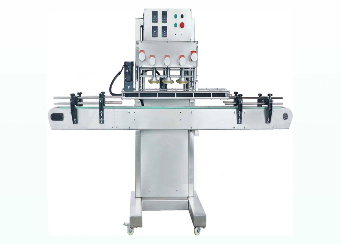
A chuck capper applies a matched tool from above to tighten an individual closure, while a spindle or wheel capper normally moves the capped jar continuously through opposed tightening wheels. Chuck systems can provide controlled top contact and are useful where an operator or mechanism presents the lid accurately. Spindle systems suit continuous inline flow when jars and pre-placed caps can remain stable through the wheel sets.
Neither tightening method can correct a cap that arrives inverted, tilted, cross-threaded or late. Prove placement before comparing torque results.
Headline cycle rate is not the decision by itself. Compare accepted jars per minute during refills, stops, restarts and normal variation.
Use the smallest and largest jars, every closure family and the least stable or most mark-sensitive approved format.
| Decision factor | Chuck tightening | Spindle or wheel tightening |
|---|---|---|
| How torque is applied | A shaped chuck contacts the closure from above during a defined tightening cycle. | Opposed rotating wheels contact the closure as the jar travels through the machine. |
| Jar movement | The jar is commonly stopped or indexed while tightening takes place. | The jar commonly remains in continuous inline motion. |
| Closure contact | The chuck profile must suit the closure geometry and surface condition. | Wheel material, pressure, height and speed must suit the closure without slip or marking. |
| Format change | Another closure may require a different chuck, insert or height setting. | Another format may require wheel, rail, belt and height adjustments; very different caps may need change parts. |
| Cap placement | Can work with operator placement or automatic placement when the cap is presented squarely. | Usually relies on reliable pre-placement and controlled handover before the first wheel contact. |
| Line integration | Well suited to indexed or compact cells where the jar position is positively controlled. | Well suited to conveyorised lines where spacing, side belts and guide rails maintain a stable presentation. |
| Acceptance evidence | Both routes need the same pack-level evidence: correct engagement, approved torque method where relevant, closure condition, leak or integrity checks where required and sustained accepted output. | |
Lancing can compare chuck and spindle routes more usefully when the enquiry includes the complete jar and lid range, target accepted output, line layout and the checks used to release finished packs.
Request an application reviewNo. Chuck tightening can be used in manual-assisted, semi-automatic or fully automatic equipment. The important distinction is how the jar and closure are presented, held, tightened and released—not the automation label alone.
It may be possible, but suitability depends on closure geometry, wheel contact, jar stability, side-belt control and acceptable marking. Wide or shallow closures should be trialled with production samples rather than selected by diameter alone.
Neither method is automatically better. A matched chuck can concentrate contact in defined areas, while correctly selected wheel materials and settings can provide continuous tightening. Trial the real finish and agree a visible marking limit.
Yes, when the closure can be oriented, tracked and presented reliably. The feeder, chute, escapement and placement mechanism should be assessed as one system with the capper rather than as independent equipment.
The answer depends on how different the jar and cap formats are. A chuck route may need dedicated chuck tooling; a spindle route may need wheel, guide, rail, belt or cap-placement changes. Record every required part in the format matrix.
Use the same production jars, lids, conditioning time, test instrument, test direction, units and acceptance method. Compare the distribution of accepted results and failure modes, not a single isolated reading.
Send your jar, lid, product and target output. Lancing will help you identify a practical machine route and the samples needed for confirmation.