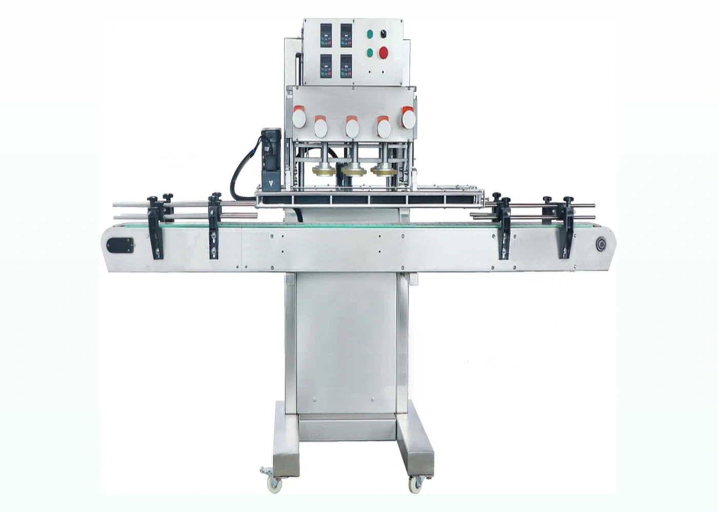
Automatic jar capper
Select the tightening or twist-off method around the closure and sustained line rate.
Explore this option
A reliable capping cell depends on the filling stage, jar transfer, cap supply, inspection and downstream handling. Review the whole flow before fixing an isolated machine speed.
Start with real samples. Your jar, lid and target output provide a more reliable recommendation than choosing by model number alone.
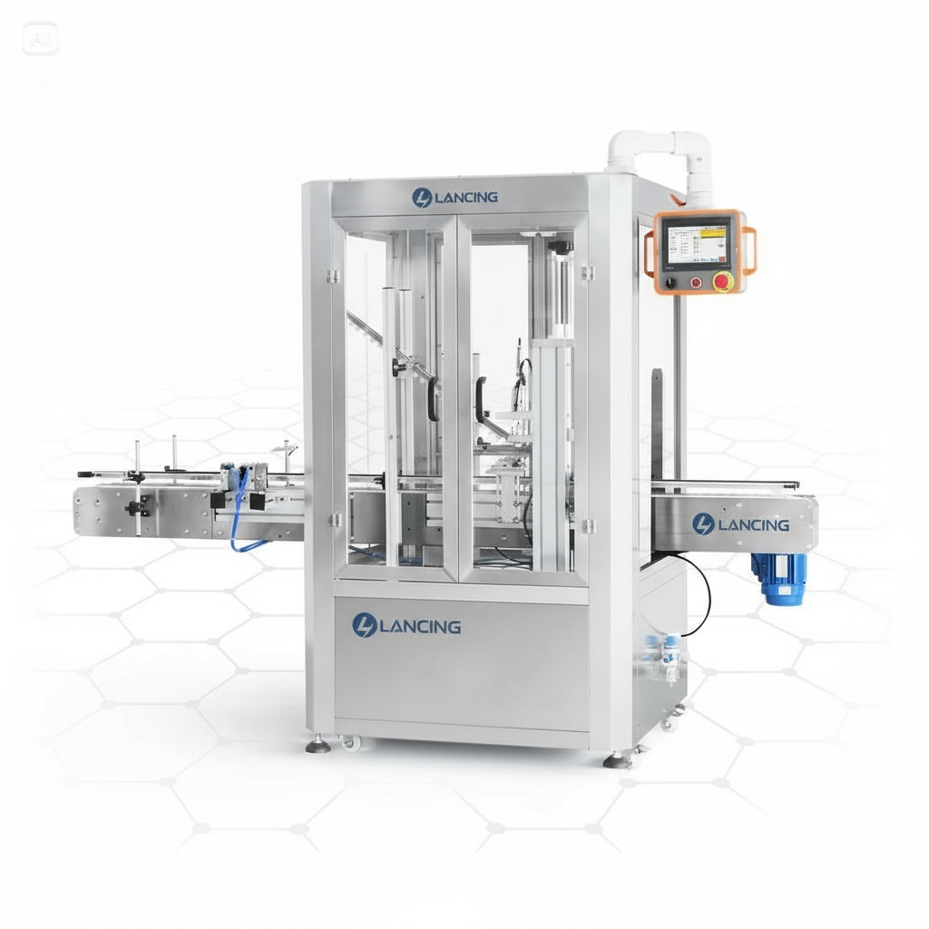
A project may start with one capper or include a complete line. Interfaces, controls and buffers should be defined as deliberately as the individual machines.
Select the tightening or twist-off method around the closure and sustained line rate.
Explore this option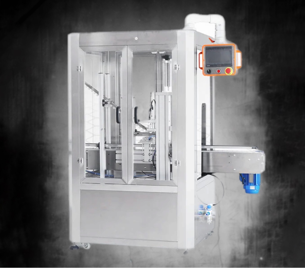
Sort, orient and present compatible lids without starving or overloading the capping station.
Explore this option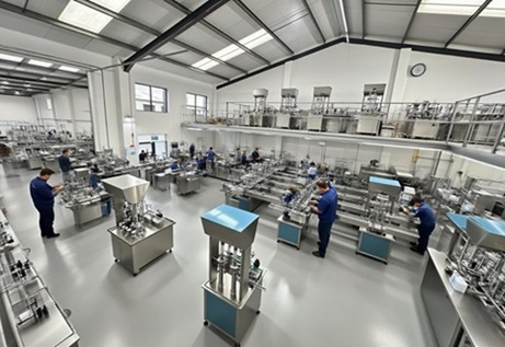
Document conveyor height, controls, footprint, utilities, upstream filler and downstream inspection.
Explore this optionShort stops at the lid feeder or capper can propagate through a line. Accumulation, machine handshake and recoverable fault logic influence real efficiency.
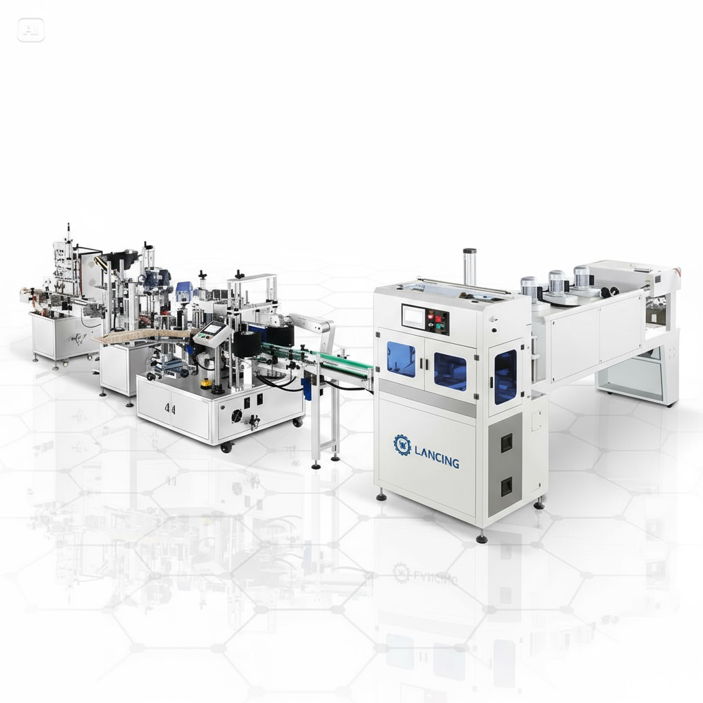
| Interface | Why it matters | What to provide |
|---|---|---|
| Filler to capper | Wet finishes and irregular jar release affect closure application. | Discharge pitch, fill accuracy, drips and conveyor height. |
| Feeder to capper | A buffer must absorb short supply variations without cap damage. | Chute capacity, low-cap detection and line stop logic. |
| Capper to inspection | Faults should be detected while packs remain traceable and rejectable. | Torque/vacuum checks, sensor position and reject method. |
| Controls | Machines need agreed permissives, stops, restart behaviour and fault ownership. | Control standard, I/O list, emergency-stop philosophy and upstream/downstream signals. |
An integrated line should have an agreed user requirement, layout, acceptance test and responsibility matrix. Assumptions about third-party equipment are a common source of delay.
Indicative dimensions and speeds are screening information, not an acceptance test.
Often, after checking conveyor height, available length, controls, jar spacing, cap feed and the performance of upstream and downstream machines.
A buffer can prevent every short stop from halting the complete line, provided the jar and product can be accumulated safely.
The contract should state module responsibilities, interfaces, test conditions and the definition of sustained line performance.
This page owns the jar-specific handovers into and out of the capper. Wider filler, labeller, conveyor, guarding and end-of-line architecture belongs in the complete-line project.
| Interface | Jar-capping requirement | Project evidence |
|---|---|---|
| Filler discharge | Stable jar pitch, controlled drips, clean finish and product condition suitable for immediate closing. | Filled samples, discharge timing, temperature and spill data. |
| Cap feed handover | Correctly oriented closure at the agreed placement point with buffer and low-cap signals. | Handover drawing, sensor list and stop/restart test. |
| Capping result | Defined torque, vacuum, cap-height, leak, button and visual methods as applicable. | Acceptance plan and retained sample set. |
| Downstream release | No collision, back-pressure or transfer that changes the closure or damages the jar. | Queue test, transfer video and reject tracking. |
| Controls | Agreed starve, block, stop, restart, fault and emergency-stop behaviour. | I/O schedule, cause-and-effect and site acceptance test. |
For full filling, capping, labelling, conveying and end-of-line coordination, continue with Packaging Lines UK. Use the jar-capping guidance to review that stage in detail, alongside the complete-line requirements.
Confirm line height, flow, access, utilities, guarding boundaries and responsibility for connected equipment.
Test starved, blocked, fault, reset and restart states as well as the normal sustained production run.
Identify signals, conveyor boundaries, accumulation, rejection, data and safety responsibilities.
Integration should control how jars, lids and machine states move through the line during normal running, starvation, blockage, rejection and restart.
Accumulation should be placed where it protects the capping process from predictable short interruptions without creating unsafe pressure or unstable jars.
A small upstream buffer may prevent cap-feeder refill from stopping the filler, while downstream accumulation may absorb label or packing interruptions. Capacity should be based on the actual stop duration, jar stability and control sequence, not simply available conveyor length.
A controlled stop sequence prevents new jars or lids entering a zone that cannot complete its cycle, while allowing safe packs already in process to clear where appropriate.
The sequence should define which machine stops first, what happens to a lid already presented, how uncapped jars are identified and how the line restarts without duplicate capping or uncontrolled release. Prove common faults during acceptance testing.
The device responsible for the final infeed spacing should control jar pitch immediately before the closing zone, coordinated with upstream release.
Depending on the design this may be a timing screw, star wheel, metering gate, side belts or conveyor control. Ownership must be explicit because poor pitch can appear as a cap-placement, sensor or torque fault.
The line should prevent an unconfirmed jar being treated as accepted product and should route or hold it according to the agreed reject philosophy.
Detection may be based on cap presence, placement confirmation or downstream inspection, but the method must suit the actual closure and line. Define reject confirmation, full-bin response and what happens after a sensor fault or manual bypass.
Provide the line layout, conveyor data, controls responsibility, upstream and downstream speeds, planned accumulation, reject method, format matrix and a written stop-and-restart sequence.
Send your jar and lid detailsA sensor can identify a possible defect, but the complete line must also associate the signal with the correct jar, remove that jar, confirm removal and respond safely when the reject path is unavailable.
| Interface | Define before layout approval | Prove during acceptance |
|---|---|---|
| Inspection trigger | Sensor position, jar tracking, format recipe and condition that creates a fail. | Known good, missing, high, cocked and deliberately failed packs as applicable. |
| Tracking distance | How the failed jar identity is maintained from inspection to reject. | Mixed good/fail sequences at normal spacing, acceleration and restart. |
| Reject device | Push, divert, air blast or other method appropriate to jar mass, stability and product. | Reliable removal without tipping neighbouring accepted jars. |
| Reject confirmation | Sensor or other evidence that the intended jar entered the reject container. | Failed confirmation causes the agreed stop or containment response. |
| Reject container | Capacity, access, guarding, segregation and full condition. | Full-bin or unavailable-bin simulation and controlled recovery. |
| Counts and records | Entered, inspected, accepted, rejected by reason and reconciled totals. | Counts remain explainable after stop, reset, manual sample and changeover. |
Use the jar-lid inspection and reject guide for method selection. Use the OEE and downtime guide to report inspection-related stops separately from capping-head losses.
State which defects are checked, whether inspection is 100% or sampled, what happens after a fault or bypass, who reconciles rejects and which packs require separate laboratory or offline testing.
Review the line interfacesWhen a jar uses a compatible foil-lined screw closure, the capper and induction sealer should be treated as connected process equipment. Jar spacing, cap application, sealer head location, cooling, inspection and reject handling all affect the finished result.
Confirm square cap placement and the approved application condition before the jar reaches the sealing field.
Control line height, jar spacing and accumulation so each pack passes through the validated sealing position during normal stops and restarts.
Define when the seal is inspected, how failed packs are contained and what happens after an alarm or loss of process.
Send your jar, lid, product and target output. Lancing will help you identify a practical machine route and the samples needed for confirmation.